
What would it take to make a 20-foot pole?
We wanted a full 20 ft (6.10 m) pole without giving up the climbing surface. A structural study found a plausible route, and exposed the much harder part: how the pole, its ends and the building would carry the load together.
Making a familiar pole twice as tall is not a matter of ordering a longer tube. Bending grows quickly with span. A joint halfway up can add motion and fatigue risk precisely where a performer expects a continuous grip. A large diameter might solve one problem by changing the product people hold.
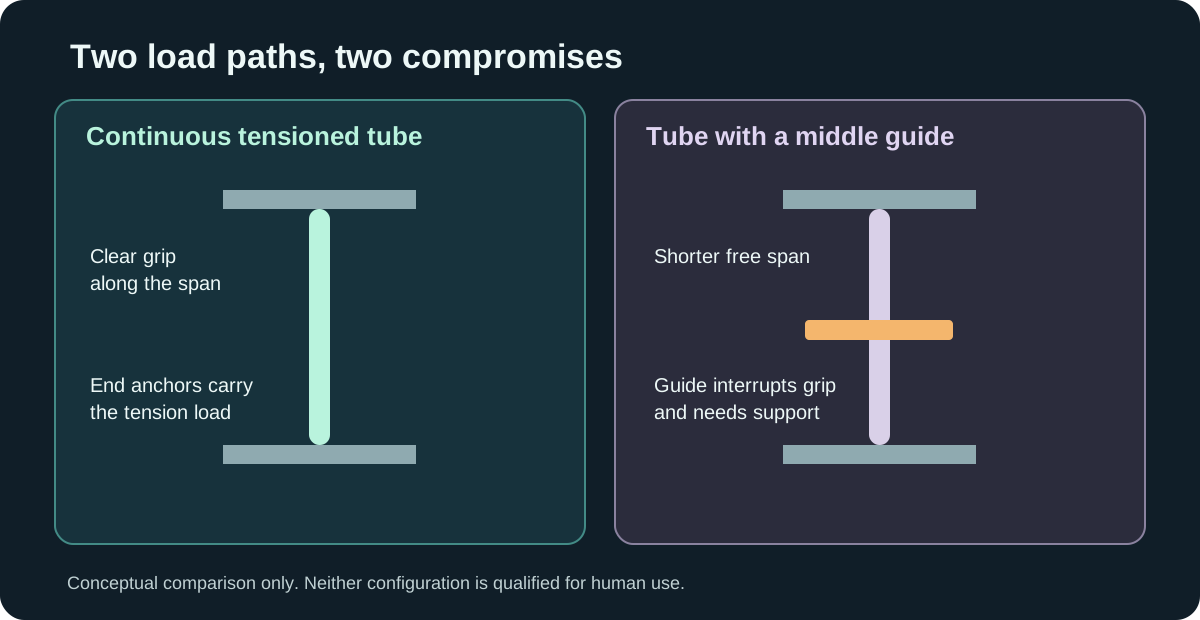
Our September design study kept the primary steel outside diameter at 1.500 in (38.10 mm) and compared three families of solutions: a larger or stiffer member, a support near the middle, and a continuous member held in controlled axial tension. A middle guide can steady the pole, but it interrupts the climb. A cable or stay moves into the performer's space. The continuous tensioned tube was the most promising way to preserve access along the pole.
The load moves to the ends
Pulling a slender tube tight can reduce sideways movement. It does not make the forces disappear. They arrive at the upper and lower fittings and then at the building. The studied concept uses a new thick-wall steel tube, positive metal capture at both ends, and purpose-designed supports. Its analytical load path approaches 8,000 lbf (36 kN) at an adverse end and building interface. Existing bearings, screws, collars and adhesive have not been credited with carrying that load.
The study also distinguishes a 20 ft (6.10 m) overall installation from 20 ft of unobstructed handhold. End housings consume height. A genuinely clear 20 ft surface requires more room and longer stock. The existing illuminated section does not magically become 20 ft long either; electrical routing and serviceability are separate design work.
Under the study's nominal 20 rpm, 18 in (457 mm) orbit and 2g catch assumptions, the proposed configuration stayed within provisional movement proxies. A faster 30 rpm routine case exceeded the 1 in (25.4 mm) proxy; a combined wider-radius 3g catch and orbit case exceeded the 2 in (50.8 mm) proxy. These assumed loads are not measured performer limits. The proxies help rank concepts, but they do not tell us how the pole feels. The specified comparison with an existing pole under matched mounting and loading is still open. Real performance loads, end-detail fatigue, material certification, anchor stiffness, failure containment and installation variability all need evidence.
The answer we actually have
There is a credible conditional design path for a continuous pole at the intended diameter. There is no qualified 20 ft PoleFX product from this work, no approval for human use, and no safe installation recipe in these calculations. The current pole was not demonstrated capable of this span.
The next decision is whether the venue anchorage and long-stock handling are acceptable constraints. If they are, the next work is material and end-detail testing, a measured load spectrum, a matched stiffness comparison, and an independent review of the whole building-to-building load path. Any failed condition sends us back to the architecture, not to a more confident headline.